Time to read: 13 min
Today’s product complexity, along with increasing downward pressure on overall pricing, has led to an inevitable increase in the geometric complexity of mechanical components. The increased geometric complexity allows components to be utilized in an advanced way, typically performing multiple functions. This multi-functional utilization has led to complex load transfers, resulting in new stress concentrations. In 2022, the pressure to design components that can run for the longest number of cycles at the lowest price is significantly demanding.
A stress concentration is defined as high localized stress, compared to the average stress of the body, and is typically found in a region that has an abrupt geometric change or discontinuity. The body tends to fail at the location of a high-stress concentration or stress riser. This article will walk through the basics of stress concentration, offer real-world examples to illustrate the concept and outline methods for reducing stress concentrations in your designs.
Stress Concentration Factor
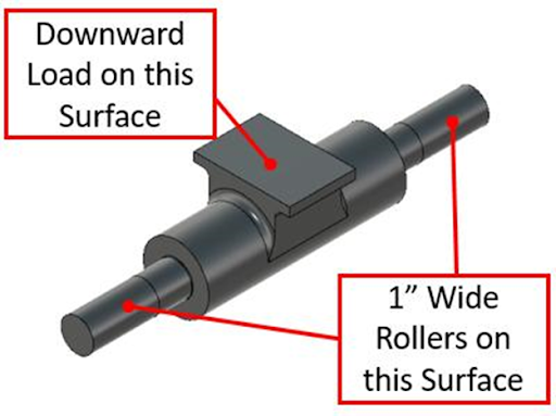
The effect of a stress riser can be determined quantitatively, utilizing mathematical methods such as the stress concentration factor. The stress concentration factor, Kt, can be defined as the ratio of the highest stress in the part to the reference stress, expressed as the following mathematical equation. Stress concentrations are relatively straightforward when it comes to identifying where they will be located and whether they have contributed to the failure. They will be located in the small radii and sharp corners that are in a load path. The image below shows a component that will have rollers on the smaller diameter shafts on both ends, with a load applied to the top flat surface.

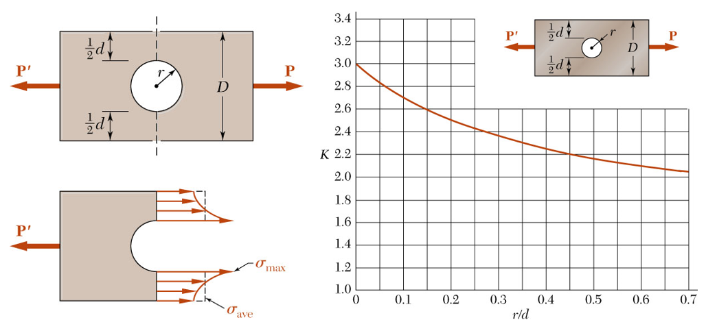
The stress concentration factor is dependent on the geometry of the part. Components with more significant discontinuities in geometry will have higher stress concentration factors. See Figure 1 for an example of the average versus maximum stress:
Stress Concentration-It’s All Geometry
Determining the location of stress concentrations and identifying whether they tend to cause failure is a relatively straightforward process. For example, there will be a stress concentration in geometric features such as small radii or sharp corners that are in a load path. A reduction in stress concentration can be achieved with the utilization of certain CNC (Computer Numerical Control) machining techniques. CNC machining is a powerful tool to reduce stress concentrations because you seamlessly design and machine in stress flow points like relief notches and a reduction in sharp corners.
Figure 2 shows a component that has been designed with rollers on the smaller diameter shafts on both ends, with a load applied to the top flat surface.
Stress Concentration-Simple Loading
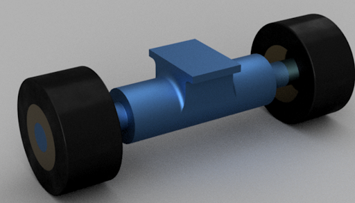
This setup will almost behave like skateboard trucks, but we’ll be leading to a higher force that is cyclic. Figure 3is a rendering of the subassembly that this component goes into, including the rollers with bearings.
Download the Complete Guide to Designing Tight Tolerance Parts
Now we can see that the smaller diameter shafts meet the center portion of our roller support with a relatively abrupt radius. If we zoom in on this radius, we can see that it comes in at only 0.010”, as shown in Figure 4.
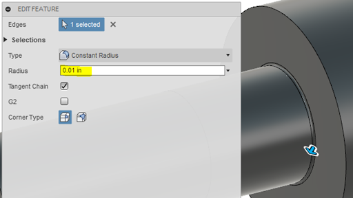
As previously mentioned, a sharp corner or radius will be the location of a stress concentration. To visualize this stress concentration, we will review stress distribution. Figure 5 shows the loads and constraints utilized for the FEA analysis of the previously discussed part.
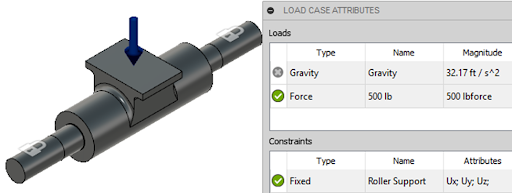
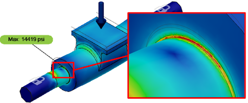
The assembly is loaded with a downward force of 500 lbs, and the surfaces of the shaft where the rollers would sit have been fixed. Next, the FEA software is run to display the stress, due to the load, throughout the assembly. Figure 6 depicts the stress concentration where blue has the lowest stress value and red is the highest.
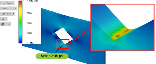
From Figure 6, we can see that the sharp radius is the location with the highest stress concentration. Due to the localized, high-stress concentration, this area would be the first location to fail under cyclic loading (though it would most likely occur on the bottom side-loaded in tension, instead of the top compressive side). A failure of this type would initiate as a small surface crack that eventually propagated through the component to complete failure.
Stress Concentration-Bending Moment
The mathematical relationship for the maximum stress, stress concentration factor, and average stress when a body is experiencing a bending moment is the same as the formula for stresses under normal loading conditions. The formula, in this case, is as follows:
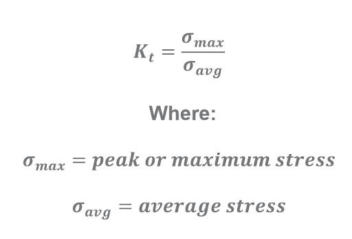
For bending moments that are acting upon bodies with the simplest geometries, the stress concentration factor can be defined based on the ratio of the corner radius and the critical part dimensions. Figure 7 shows the curves of these geometry-dependent stress factors.
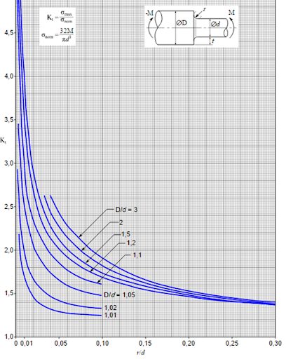
How to Utilize a Geometric Curve to Determine Stress Concentration Factors
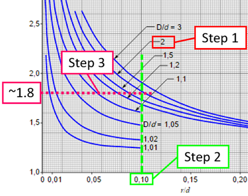
To utilize the chart in Figure 7, the first step is to divide the large diameter by the smaller diameter i.e. have a larger diameter rod with a step-down to a 1-inch diameter rod gives: D/d=2/1=2.
The second step is to look at the ratio of the radius to the smaller diameter. For example, if the radius is 0.1 inches and the smaller diameter is still one inch, this gives an r/d ratio of 0.1. If we look at the chart above, we need to find the curve that represents a D/d of 2. The third step is to look at the x-axis to locate the r/d of 0.1 and look across to the Y-axis to get a stress concentration factor of about 1.8.
Figure 8 depicts the three steps of determining the stress concentration factor in a graphical format.
It’s important to note that this formula changes based on the load case and geometry, so further charts will need to be utilized for additional geometries. A good resource for finding curves for other geometries is “Peterson’s Stress Concentration Factors, 4th Edition”. Now that we understand the basics, we can step into some examples of correcting stress concentrations.
Real-World Examples
In this section we’ll look at how we can reduce the peak stresses at the location of the stress concentration, utilizing real-world examples.
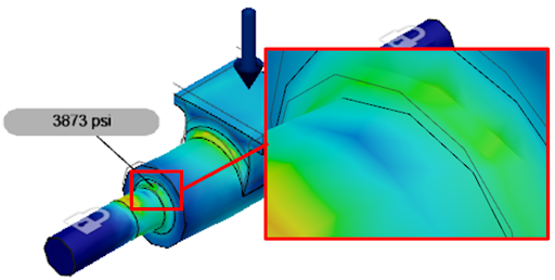
The first example we’ll look at is our original component shown in Figure 3. If you recall, we had a very small 0.01” radius at the step-up in diameters. Now, we’re going to increase that diameter to 0.08” to see how much we can reduce the stresses.
Figure 9 shows the original stresses, and Figure 10 depicts the reduced stresses with a larger radius. We can see that the stresses have gone from 14,419 psi down to 3,873 psi. While this differential is pretty extreme because of the extremely small original radius, it drives the point home of just how much a stress concentration can influence the stresses in the part.
In the next two examples, we’ll look at some geometries with a tensile load applied, instead of a bending moment. The first part is a support bracket that holds a brass pin. The brass pin typically has an upward load applied, and the base is bolted to a fixed plate, as shown in Figure 11.
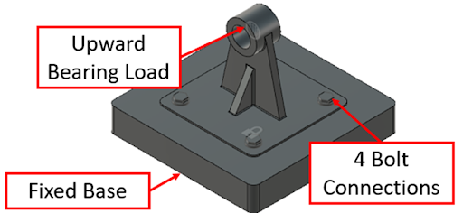
FEA was run for this assembly, as previously discussed, to obtain baseline stress distribution values, before performing any design changes. The results of the FEA are depicted in Figure 12.
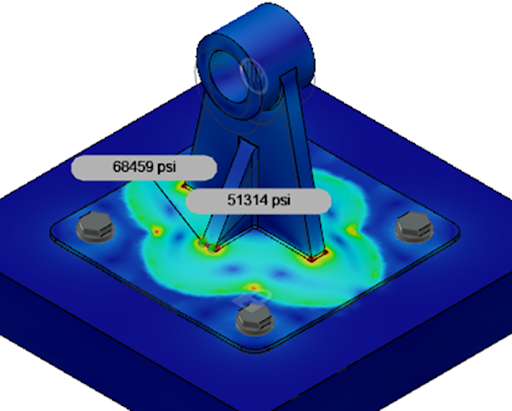
The stresses at the base with the small radii (0.030”) are a high concentration, ranging above 68,0000 psi. As previously shown, a larger radius should help lower the stresses here, even with a much different load case and geometry.
For the FEA simulation in Figure 13, the small radii have been increased from 0.030” to 0.080”, and the resulting stress is much lower.
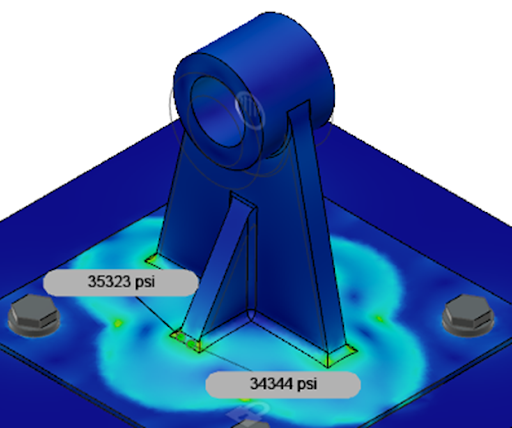
To obtain even lower stress values, the thickness of the flange to which this assembly is attached could be increased. This thickness increase would be effective at reducing the stress because of the light blue coloring that indicates that this geometric interface of the part is deflecting under a load.
In Figure 14, we have a flat plate with a diamond-shaped hole cut out of the center. There is a load applied on one end, while the other end is fixed, as shown in Figure 14.
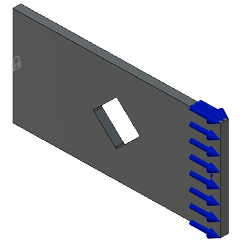
From the FEA depictions showing stress concentrations previously, you might have correctly anticipated that the highest stresses will be located at the top and bottom corners of the diamond-shaped hole. Figure 15 shows the results of this simulation.
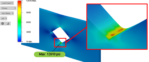
From Figure 15 the highest stress concentration is exactly where we expected. To reduce the stress concentration, we could modify the hole to have a bigger radius, or drilling that hole out to result in a circular shape. Utilizing a circular shape would reduce the overall part material while lowering the stresses. As shown in Figure 16, the same simulation was run with a round hole that is greater in diameter than the distance from the top to the bottom of the diamond-shaped hole above.
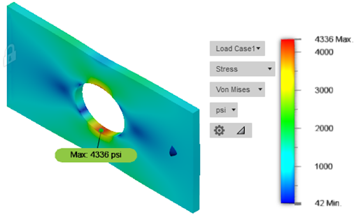
We can see that while the stress region is larger, the magnitude of peak stress is roughly 1/3 of the original case. In a similar approach but different application, it is common for repair centers to drill a hole at the end of a crack to relieve the high-stress concentration associated with the very small radius at the tip of a crack.
By now, the idea of locating and mitigating the risk of stress concentrations should be clearly defined. While the FEA program was utilized here to determine the magnitude of stresses, the same general guidelines can be used to improve a design.
General Design Tips and Issues to Avoid
When it comes to common methods of reducing stress, the following list includes some simple guidelines to follow:
- Make radii in a load path as large as possible.
- Limit the ratio of the large feature to the small feature.
- Add stress-reducing holes at the end of slits, sharp angles, or cracks to relieve high-stress concentrations.
- Refer to stress concentration charts to understand when you are in a region of diminishing returns concerning radius size.
Some common issues to avoid are:
- Do not use sharp corners along a load path.
- Do not make a large-size transition between loaded features. The stiffness mismatch will drive the stress concentration much higher.
- Don’t assume that the same size radius works for all features. Remember that the stress concentration is based on a ratio, not a magnitude.
- Don’t place a stress concentration in a high cyclic load if you absolutely must use a sharp corner.
As you may have guessed, most of the “don’ts” are inverse to the “dos”. This list is not fully comprehensive, but it should cover the basic concepts and design tips that every designer should know to improve their design skills. Understanding the stress concentration effect on product or component longevity is important in areas like stress concentration in machine design.
Through the examples and analysis above, it should be clear exactly why we need to be concerned with stress concentrations. By incorporating these concepts through your design, you should be able to achieve higher load ratings, reliability, and fatigue life.
I encourage design teams to talk through product requirements and design tips and choices to ensure the proper blend of aesthetics and function while mitigating the effect of stress concentration. There will always be tradeoffs, but proper analysis can help achieve an optimized solution.
Stress Concentration FAQs:
- Stress concentrations occur because of abrupt changes in geometry, such as a sharp radius or edge.
- As the radius of curvature approaches zero, the stress concentration factor approaches infinity. Increase the radius of curvature to reduce the stress concentration factor.
- The stress concentration factor is generally calculated by dividing the maximum stress by the average stress in a member, under loading.
- A fillet provides lower stress concentration than a chamfer.
- A stress concentration factor is a ratio of the maximum stress in a member to the average stress in a member.
